SWSWUTILITIESADVANCED RTP PIPELINE SOLUTIONS
SWUtilities product programme

RTP specifications

Proposed design envelopes for standard, produced water, hydrocarbon, gas, hydrogen, downhole and Smart RTP. Select the complete pipe and fitting system for each duty. SWUtilities can support the full turnkey scope from supply through installation and testing.

2″–8″Nominal programme size range
Up to 5,000 psiMaximum development target, not every size
Up to 120°CSpecialist temperature design study target
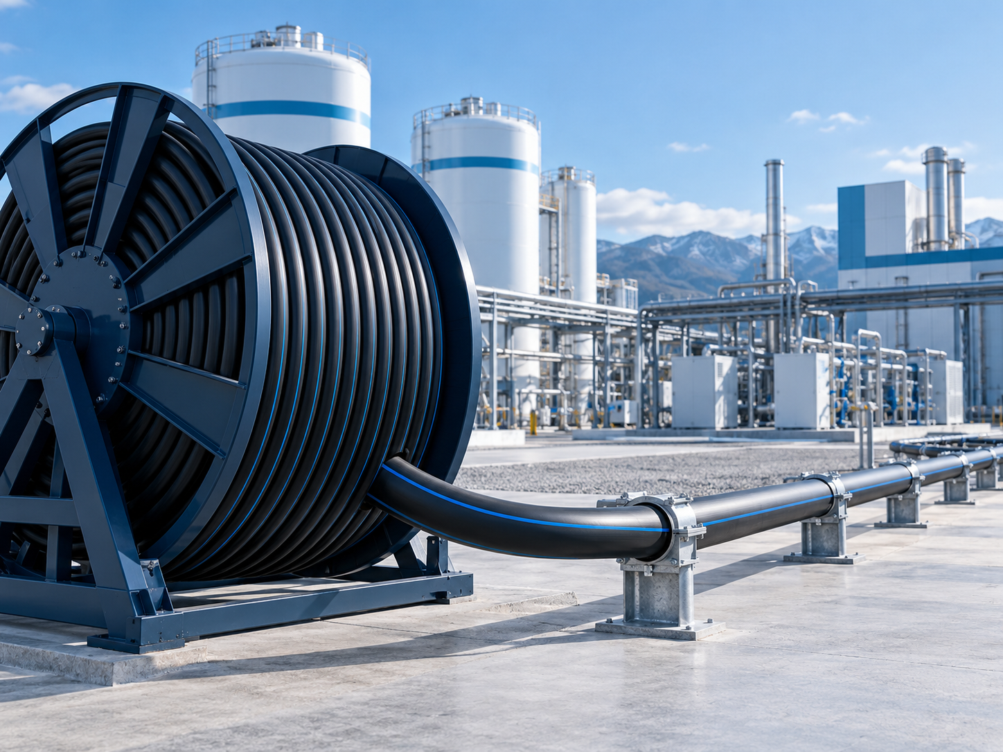
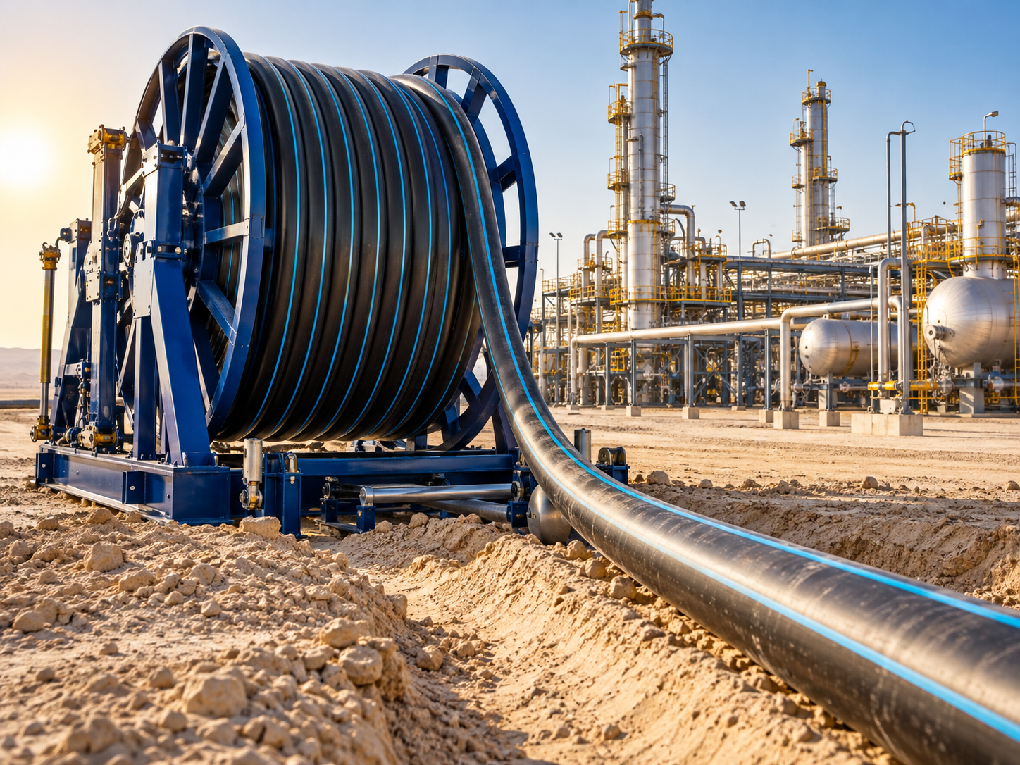
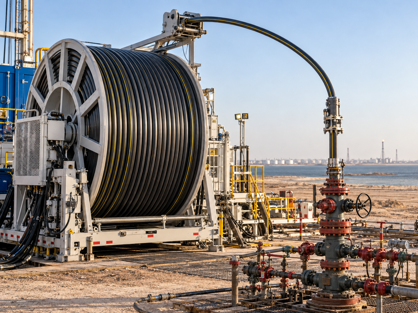
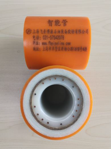
Concept imagery for hydrogen RTPConcept imagery for gas RTPConcept imagery for downhole RTPShanghai F.B Oil Equipment intelligent composite pipe sample and cross section
Smart RTP sample photo: Shanghai F.B Oil Equipment, via JEC Composites
Application matrix

Design targets by service

These figures describe a proposed portfolio. They are not product datasheets or certified operating ratings.

RTP familyIndicative serviceNominal sizePressure targetTemperature study window
Standard RTPSurface line pipeNonpotable water and suitable industrial fluids2″–8″Application dependent, within 5,000 psi programme ceilingStandard grade: up to 60°C target
Hydrocarbon RTPSurface line pipeQualified liquid hydrocarbons and multiphase duty2″–8″, by designApplication dependent, within 5,000 psi ceilingHigh temperature grade: up to 85°C target
Produced water RTPSurface line pipeProduced water transfer and reinjection networks2″–8″, by designApplication dependent, within 5,000 psi ceilingUp to 85°C target, chemistry dependent
Gas RTPGas containment designQualified natural gas and associated gas transport2″–8″, subject to qualificationApplication dependent, within 5,000 psi ceilingTo be qualified; study target up to 85°C
Hydrogen RTPBarrier developmentHydrogen transport concepts with permeation control2″–8″ programme ambitionTo be qualified within 5,000 psi ceilingTo be qualified for gas composition and duty
Downhole RTPSpecialist well serviceSelected downhole deployment conceptsSize selected for well geometry; 2″–8″ programme does not imply all downhole sizesUp to 5,000 psi study target; external pressure and axial loads assessed separatelyUp to 120°C development target, subject to long-term qualification
Smart RTPIntegrated utility pathwaysPipeline system with protected provision for electrical power and communications; optional temperature control where required2″–8″ programme range, by engineered designBase pipe rating to be qualified within 5,000 psi ceilingBase pipe temperature rating plus separate thermal and electrical qualification
How to read the envelope5,000 psi and 120°C are separate maximum development targets. They do not describe one pipe that is available at every diameter, fluid, temperature, depth or pressure. A released product datasheet must state the rated combination and service life.
Design images

Conceptual pipe constructions

Layer selections show design directions only. Final materials, layer thicknesses and joints require engineering and qualification.

Standard and water RTP

Corrosion resistant liner with reinforcement and a protective jacket for suitable surface utility and water duty.

Concept pipe layer arrangementBOREConcept diagram · not to scale
Inner liner: PE100-RC or application-specific polymer
Reinforcement: Glass or aramid concept
Outer jacket: UV resistant PE concept

Gas and hydrogen RTP

A gas barrier and qualified end fittings address containment and permeation as part of the complete system.

Concept pipe layer arrangementBOREConcept diagram · not to scale
Inner liner: PA or other qualified polymer
Gas barrier: Candidate barrier, subject to permeation testing
Reinforcement: Aramid, glass or carbon concept
Outer jacket: Application-specific protection

Downhole RTP

Specialist construction must account for temperature, pressure cycling, axial load, crush and deployment.

Concept pipe layer arrangementBOREConcept diagram · not to scale
Inner liner: PA or PVDF concept
Gas barrier: Optional, where gas service requires it
Reinforcement: High-strength fibre concept
Outer jacket: Abrasion and well-fluid resistant concept

Smart RTP

Protected power and communications routes can be incorporated with the pipe. Optional temperature control requires a dedicated, qualified thermal and electrical design.

Concept Smart RTP layer arrangementConcept diagram · not to scale
Flow bore: service-specific liner
Reinforcement: qualified for pipe duty
Power route: protected, electrically isolated
Communications: fibre or cable provision
Temperature control: optional engineered system
Qualification basis

What defines the final rating

Pressure and temperature together

Establish sustained and transient pressure, temperature derating, test pressure, burst margin and design life for each diameter.

Fluid and gas compatibility

Check liner and barrier chemistry, gas permeation, decompression and long-term exposure to the actual fluid mixture.

Pipe, fittings and installation

Qualify joints, bend radius, axial tension, supports, burial, handling and field test methods as one system.

Smart system interfaces

Validate electrical isolation, cable protection, thermal control, joints, monitoring interfaces and maintainability as part of the full pipe assembly.

Downhole conditions

Assess internal and external pressure, collapse, tensile load, cycling, well fluids and retrieval before any well service rating.

API Spec 15S covers manufacture and qualification of spoolable reinforced plastic line pipe for energy applications. Downhole, hydrogen and Smart RTP functions need additional duty-specific qualification and approvals. API standards programme